41+ Buzzer Wiring Diagram Temperature Pictures. The objective of this esp32 arduino tutorial is to explain how to control a buzzer with the esp32 waterproof ds18b20 digital temperature sensor for arduino. The buzzer in your inventor's kit is an electromechanical component you can use to make noise.
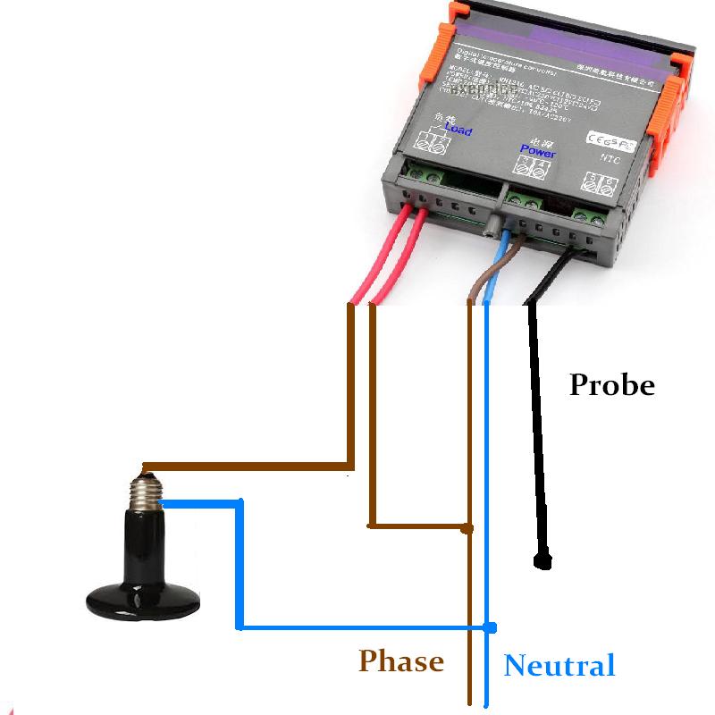
Digital thermostat stc-1000 (wilhi) diagram schematic ... from usefulldata.com Note that the external wiring diagram in this sensors and wiring section is entirely separate from, though similar to, the relay board. Remote switch control panel w. It is used to produce an output sound corresponding to the electrical energy in the input.
It's simple, tone(buzzer, 1000) sends a 1khz sound signal to pin 9, delay(1000) pause the program for one second and notone(buzzer) stops the signal sound.
Note that the external wiring diagram in this sensors and wiring section is entirely separate from, though similar to, the relay board. How to use this manual b. Dht11 temperature and humidity sensor. Mgb, mgc, mgbv8 wiring diagrams.
Bagikan Artikel ini
Belum ada Komentar untuk "Buzzer Wiring Diagram Temperature"

Belum ada Komentar untuk "Buzzer Wiring Diagram Temperature"
Posting Komentar